Audio Processing on the RaspberryPi
Scope
The Raspberry Pi (RPI) shall be used as a sound surveillance system with the following features:
- A microphone records audio samples in some kind of cyclic buffer.
- The audio samples are repeatedly evaluated to detect sound events.
- A sound event is characterised by a time slot in which the audio activity exceeds some threshold.
- The RPI may then react to a sound event above such threshold like this:
- A notification is sent to a PC connected to RPI via a wireless connection.
- The RPI stores audio samples into a file. The time interval of this audio record shall be in the vicinity of the time instant where the sound event had occurred.
- The PC may then download the audio file for further signal processing/analysis
Basically the sound surveillance system may be decomposed into two building blocks:
- Capturing and processing of audio samples
- Control interface
- interacting with the RPI via wireless link
- configuring the application on the RPI
- starting and stopping the application
- data retrieval
- postprocessing of audio data on PC (motivation: the RPI shall act as a data collector; more time consuming operations are delegated to the PC).
Some more details are presented here. Specific sections will deal with implementation details.
Capturing audio samples
Hardware
The capturing of audio samples on the RPI shall use standard components which should not only work on the RPI but as well on a Windows / Linux PC. A reasonably cheap solution has been found to work on either platform (RPI , PC). Specifically I will use a USB soundcard and a microphone attached to the soundcard. A figure shows the setup:
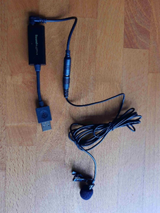
| Components | Description |
| USB Soundcard | Creative Soundblaster Play!3 |
| Microphone | Lavalier microphone |
Software
Interacting with the soundcard programmatically will be performed using Python libraries that are available on Linux and Window operating systems. The table provides an overview of what I found useful when implementing the sound processing with Python:
| Library | Description |
sounddevice | accessing the soundcard, storing audio samples, setting parameters of the soundcard (sounddevice), etc. https://python-sounddevice.readthedocs.io/en/0.4.6/ |
soundfile | reading and writing audio file with different option on the format of the audio file. https://python-soundfile.readthedocs.io/en/0.11.0/ |
Control
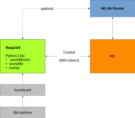
The RPI shall be controlled by a PC via a wireless link. To minimise external hardware the communication between RPI and PC shall be setup as a WiFi direct link thus not requiring an additional WLAN router. So the RPI will be setup as a hotspot with a DHCP server. The PC connects to the hotspot after the RPI has booted . The diagram provides some more details:
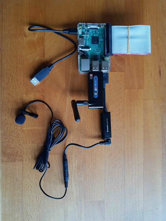
And here is a picture indicating how an external USB WiFi adapter establishes a WiFi direct link between the RPI and the PC. (The internal Wifi adapter of the RPI could still be used to connect to a WLAN router).
Note
At least the PC should have an additional wireless connection to a WLAN router to access the internet or any other devices connected to the router. This router-based connection is shown in the figure above.
Preliminary Steps
Getting familiar with
- soundprocessing with Python
- Setting up Wifi direct on RasperryPi
are prerequisites to implement a sound surveillance system for the RPI. So these topics will be addressed first before defining details how to setup a sound surveillance system.
Soundprocessing with Python
Required Software
On a Windows PC I have installed:
- Python 3.11
- Numpy
- Scipy
- Matplotlib
- soundfile
- sounddevice
On the Raspberry PI I use:
- Python 3.9 – 3.10 (depending on the version of the Raspberry Pi; currently RPI 3 (4 GB) and RPI 4 (8 GB))
- Numpy
- soundfile
- sounddevice
- plus some libraries required by soundfile, sounddevice
How to find audio devices
With
import sounddevice as sd
devices = sd.query_devices()
a dictionary of soundcards / sounddevices is returned. An example from my PC is shown here:
{'name': 'Microsoft Soundmapper - Input', 'index': 0, 'hostapi': 0, 'max_input_channels': 2, 'max_output_channels': 0, 'default_low_input_latency': 0.09, 'default_low_output_latency': 0.09, 'default_high_input_latency': 0.18, 'default_high_output_latency': 0.18, 'default_samplerate': 44100.0}

{'name': 'Mikrofon (Sound Blaster Play! 3', 'index': 1, 'hostapi': 0, 'max_input_channels': 2, 'max_output_channels': 0, 'default_low_input_latency': 0.09, 'default_low_output_latency': 0.09, 'default_high_input_latency': 0.18, 'default_high_output_latency': 0.18, 'default_samplerate': 44100.0}

{'name': 'Mikrofon (Realtek(R) Audio)', 'index': 2, 'hostapi': 0, 'max_input_channels': 2, 'max_output_channels': 0, 'default_low_input_latency': 0.09, 'default_low_output_latency': 0.09, 'default_high_input_latency': 0.18, 'default_high_output_latency': 0.18, 'default_samplerate': 44100.0}
Since we want to use the Sound Blaster device with a microphone connected to it, the appropriate sounddevice is identified by an index = 1. What is import to note is the parameter default_samplerate=44100.
Currently I assume that this is a fixed samplingrate of this specific sounddevice that cannot be reconfigured.
Selecting and configuring the audio device
For recording purposes it is sufficient to instantiate an InputStream. A code snippet shall illustrate the procedure:
iStream = sd.InputStream(samplerate=fs, device=1, channels=1, callback=wrapped_cb)This class accepts the samplingrate samplerate as a parameter. The appropriate device is configured using another parameter device. Since only recording of a single channel is required the number of channels is configured accordingly (=1). The callback parameter accepts a callback function which retrieves chunks of audio data from the sounddevice. The callback function runs at a high priority and should not be overwhelmed with lots of other postprocessing tasks.
A code snippet demonstrates the use of a callback function which only collects data and avoids any sort of postprocessing.
First a queue is set up. Audio samples will be put into this queue (FIFO).
q = queue.Queue()The call back function uses the queue variable q as its first parameter. Other parameters indata, frames, time, status are provided when called from the InputStream. Whenever a chunk of audio samples becomes available the callback is invoked and the audio samples are copied into the queue.
def callback_ref2(q, indata, frames, time, status):
    if status:
        print(status)
    q.put(indata.copy())
The callback function as defined above cannot be used directly as a callback function in InputStream. Using functools partial a new callback function wrapped_cb2 is generated. This wrapped function has only input parameters indata, frames, time, status which is the required signature of parameters by InputStream.
wrapped_cb2 = partial(callback_ref2, q)The library sounddevice offers some convenience functions to obtain a chunk of audio samples. But for more flexibility the callback based approach is recommended.
A Jupyter Notebook provides a couple of examples which demonstrate the use of the callback-based procedure.
https://github.com/michaelbiester/audio/blob/master/JupyterNb/AudioProcessing/Audio_1.ipynb
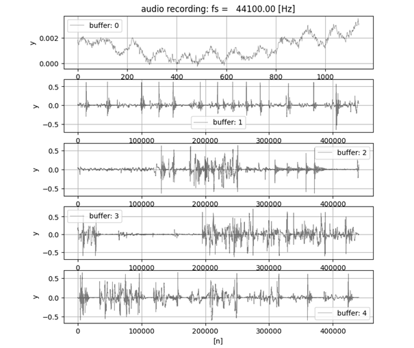
An example below shows captured audio samples. The list of 5 buffers has been set up to store audio samples. Each audio buffer is capable of storing up to 10 seconds of audio samples. (The buffers are reused in a cyclical fashion)
The oldest recording is in buffer1, followed by buffer2, buffer3 and buffer4. The most recent audio samples are in buffer0 (which only has about 1000 audio samples).
For details of the implementation look at the Jupyter Notebook.
Other sample programs
A set of example programs which have been tested on a Windows PC and the Raspberry PI can be found on GitHub.
https://github.com/michaelbiester/audio
https://github.com/michaelbiester/audio/tree/master/src
A more advanced example
This examples uses two programs:
- a client program
- a server program
Client program
The client program initiates capturing of audio data of the server program. The server program must be already running and listening to a request from the client program. The client tries to connect to the server by establishing a websocket connection. If such a connection has been successful the server begins capturing audio data. The client may enable the server program to download audio files from the computer running the server program to the computer running the client program. Typically client and server programs are running on different platforms. Data exchange uses a wireless websocket connection.
Server program
The server programs captures audio data and implements a sound detector which generates sound events if the sound activity exceeds some user specified thresholds (configurable via configuration file). The server sends various notifications to the client if these events occur:
- a sound event has been detected
- audio data have been saved to a file on the computer which runs the server program
- audio file available ready for download by the client program (if the client has configured the server to enable such downloads)
Flow of information
The figure provides an overview of the flow of information exchanged between client and server program.

The client and server program can be accessed from GitHub.
https://github.com/michaelbiester/audio
Setting up WiFi Direct on a Raspberry PI
As outlined in the overview section a WiFi direct connection between the Raspberry Pi and the PC shall be setup. Here are the steps I had to follow to make it work:
Does the PC support Wifi direct ?
On the Windows PC it is checked whether WiFi direct is supported at all. The required information is obtained using command ipconfig /all.
C:\Users\micha>ipconfig /all

Windows-IP-Konfiguration

   Hostname  . . . . . . . . . . . . : hp_mbi1955
   Primäres DNS-Suffix . . . . . . . :
   Knotentyp . . . . . . . . . . . . : Hybrid
   IP-Routing aktiviert  . . . . . . : Nein
   WINS-Proxy aktiviert  . . . . . . : Nein

Drahtlos-LAN-Adapter LAN-Verbindung* 1:

   Medienstatus. . . . . . . . . . . : Medium getrennt
   Verbindungsspezifisches DNS-Suffix:
   Beschreibung. . . . . . . . . . . : Microsoft Wi-Fi Direct Virtual Adapter
   Physische Adresse . . . . . . . . : 62-E9-AA-18-79-45
   DHCP aktiviert. . . . . . . . . . : Ja
   Autokonfiguration aktiviert . . . : Ja

Drahtlos-LAN-Adapter LAN-Verbindung* 2:

   Medienstatus. . . . . . . . . . . : Medium getrennt
   Verbindungsspezifisches DNS-Suffix:
   Beschreibung. . . . . . . . . . . : Microsoft Wi-Fi Direct Virtual Adapter #2
   Physische Adresse . . . . . . . . : E2-E9-AA-18-79-45
   DHCP aktiviert. . . . . . . . . . : Nein
   Autokonfiguration aktiviert . . . : Ja
The listing shows that this PC has 2 WLAN connection both of which support Wifi Direct.
Using the network manager on the Raspberry PI to setup Wifi Direct
First it must be checked whether the network manager is installed and enabled.
On my Raspberry Pi the network manager tool nmcli was already installed. However it had to be enabled. This is done using the raspi-config tool. It is started with
sudo raspi-configThe documentation of the raspi-config tool can be found here:
https://www.raspberrypi.com/documentation/
and specifically here:
https://www.raspberrypi.com/documentation/computers/configuration.html
The RPI has a built in WLAN adapter which shows up as interface wlan0. For the Wifi connection an external USB WLAN adapter has been attached to the RPI. This interface shows up as wlan1.
With the command nmcli the hotspot is configured like this (user specific information has been highlighted):
sudo nmcli device wifi hotspot ssid rpi3_mbi1955_hotspot password <my password> ifname wlan1With command ifconfig the status is checked and the interface wlan1 shows up like this:
wlan1: flags=4163<UP,BROADCAST,RUNNING,MULTICAST>  mtu 1500
        inet 10.42.0.1  netmask 255.255.255.0  broadcast 10.42.0.255
        inet6 fe80::20c:aff:fe68:8cb  prefixlen 64  scopeid 0x20<link>
        ether 00:0c:0a:68:08:cb  txqueuelen 1000  (Ethernet)
        RX packets 0  bytes 0 (0.0 B)
        RX errors 0  dropped 0  overruns 0  frame 0
        TX packets 46  bytes 6440 (6.2 KiB)
        TX errors 0  dropped 0 overruns 0  carrier 0  collisions 0
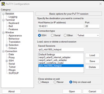
The important information here is that the WLAN interface has been assigned a local IP-address 10.42.0.1 /24.
Using address the PC can connect to the RPI (eg.: logging in via SSH).
At this point the hotspot is not setup permanently. To do this I found some extremely helpful documentation here:
https://www.raspberrypi.com/tutorials/host-a-hotel-wifi-hotspot/
From this document we learn that the autoconnect property must be set to yes and the autoconnect-priority must be changed to a high value.
sudo nmcli connection modify <hotspot UUID> connection.autoconnect yes connection.autoconnect-priority 100The hotspot UUID is queried using nmcli :
mbi1955@raspberrypi:~ $ sudo nmcli device
DEVICE TYPE STATE CONNECTION
wlan1 wifi connected Hotspot
wlan0 wifi connected Vodafone-8293
p2p-dev-wlan0 wifi-p2p disconnected --
eth0 ethernet unavailable --
lo loopback unmanaged --
mbi1955@raspberrypi:~ $ sudo nmcli connect
NAME UUID TYPE DEVICE
Hotspot c95711aa-efc2-468e-8b3f-5e2315a5bab1 wifi wlan1
Vodafone-8293 f511c832-9ad2-432d-90cc-78e311691db4 wifi wlan0
Wired connection 1 b156082b-36c4-3424-b038-4ab041dc7550 ethernet Clearly the two WLAN adapters show up with their respective UUIDs.
With
nmcli connection show c95711aa-efc2-468e-8b3f-5e2315a5bab1the properties of the hotspot connection are displayed.
With
nmcli connection show c95711aa-efc2-468e-8b3f-5e2315a5bab1 > hotspot.txtthe properties are collected into a text file.
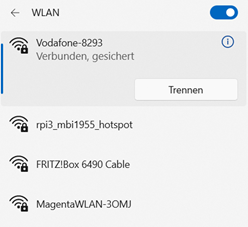
When the PC scans for available WLANs it also displays the SSID of the hotspot rpi3_mbi1955_hotspot.
Once the PC has connected (user credentials must be entered) it is possible to login via SSH. The screenshot shows the procedure if PutTTy is used.
Documention
A comprehensive documentation of the tool nmcli can be found in various places. I found the following resources quite readable:
https://developer-old.gnome.org/NetworkManager/stable/nmcli.html
https://manpages.ubuntu.com/manpages/trusty/man1/nmcli.1.html
